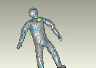
ART 397A
Digital Hand
T/TH 11:15-2:15
COLLURA
CRIT PROJECT 2:
MODEL
(ShapeShifter/Borderline/CONTROL)
(3D Modeling, Scanning, and Printing)
Bullets to take notes on:
How to prepare a model for scanning:
➢ Matt surfaces (VS. Glossy)
➢ Pins- matt surface
➢ Upright, secure
How to properly secure the Minolta scanner to the tripod
How to scan from Minolta
➢ Point Cloud Clean Up (if neede)
➢ Select options that are available (rectangle/paint brush)
POST SCANS ( although more scans are possible to take while in Geomagic> HARD-WARE>MINOLTA)
➢ Manual Registration:
o N point registration
o Register
o Modify
➢ Select Group file (and subsequent file)
➢ Global registration
o Execute overlap reduction
o Green is good!
➢ Polygon Point Cloud (even though your registered, they are still a group of individual point clouds) :
o Combine points
o Merge
o Wrap
o Note: WRAPPING TURN THE POINT CLOUDS INTO POLYGON SURFACES (if you wish to see them as point clouds go under display and check point cloud)
➢ Mesh Doctor vs singular alterations
o Analyze holes/spikes/etc
o Shoot for zero
➢ *Geomagic will save a file as a .asc file IF you wish to import to RHINO- Save as .obj file
➢ *Import into Rhino
➢ *Check Dimensions (liner dimensions) Scale Up, down
➢ *Boolean and Construction operations in Rhino
➢ *Mesh All (remember, the more polygons your mesh has, the more memery and time it will take to process). I advise to reduce your mesh (MeshEditTools) and SAVE OFTEN
➢ *Analyze shape- to reduce packing material amount in RP process, cut object into parts, if necessary (by using cutting planes in Geomagic or Rhino)
➢ *Check Edges- “naked Edges” Explode, select, erase, join
➢ Import conjoined Mesh back into Geomagic (save as .3ds)
➢ Decimate polygons to bring down file size
➢ Customize Mesh Doctor for “watertight” .STL
➢ To print from Stratysus (ABS Plastic) or ZCorp (powder print)
• Exporting and Naming your File:
• Export as STL and be sure to name your files using this format: date_userID_filename
That would be: 2011-01-12_jrh225_example1.stl for example.
• The Printing software does accept other file formats, but STL has proven to be the most reliable. If you get an error exporting, you know there are things to be fixed in your model. If your modeling software does not support STL export, consult Jamie Heilman or the DigiFab Assistants for a workaround.
•
• Check File: Verify that your file will be printable before submitting! Open your STL in ZPrint (this software is installed on all Windows computers in SALA). ZPrint is the soft-ware we use to 3D print. Importing to ZPrint yourself will save time by making problems apparent to you immediately. See the "3D Printing Intro" video tutorial. In ZPrint you can also get an estimate of how much powder and binder will be needed, allowing you to calculate the approximate printing cost.
• For THE ZCORP: The cost is $1.33 per cubic inch of powder and $0.18 per mL of binder.
• FOR THE STRATYSUS: the cost is $5.20 per cubic inch
• Submit Your File: You may submit files as STL or ZPrint.
Upload your file to the SALA server. In the “DigiFab_Lab” share you will find a folder for “ZCorp_3D_Printer”. (or Stratyus)
Drop your file in “Submit Files Here”.
• The path to get to the SALA server is: caa-sala-odmsrv.sala.psu.edu/Digifab_Lab/ZCorp 3D Printer/Submit Files Here
•
• Send Email to digifab@psu.edu: To let us know that you have submitted a file to be printed. We will check your file for printability and provide you with a cost estimate to approve before printing. To accelerate this process, include an approved maximum cost. Prints will be done on a first come first serve basis. digifab@psu.edu
•
• 24 Hour Minimum Time: You must allow a minimum of 24 hours for completion. If there are several files queued for printing, you may need to wait much longer. Plan ahead—especially during mid-semester crits and finals!
➢ IF printing via Stratyus:
o Bring file into 3D printer (Dimension 4.0) software, determine resolution, packing material type (basic/minimal/break away), quantity, and pack orientation
➢ Special Notes:
FILE CONVERSIONS:
Minolta scans save into Geomagic as ==>asc files
Geomagic ==>Rhino==>.obj file
Rhino==>Geomagic ==>.3ds file
Geomagic (or Rhino) to Stratyus or Zcorp==>.stl file
➢ When in Sculpture’s Tech room: logging into Geomagic, please type the network num-ber: 146.186.186.25
➢ Sculpture Tech has 2 (TWO) seats of Geomagic that can be used at one time. SALA has three seats. PLAN ACCORDINGLY. In the beginning, when you are learning, work with another.
➢ You all have swipe access to the room in SALA’s basement that right now houses the scanner (SOON IT WILL BE HEADING UPSTAIRS TO THE LAB), however the scanner will be locked up. If you need additional scanning time, Jamie has assistants working:
Sun 1pm-5pm, 6pm-10pm
Mon 6pm-9pm
Tues 6pm-10pm
Wed 6pm-10pm
Thurs 6pm-10pm
Fri 6pm-10pm
Sat 1pm-5pm, 6pm-8pm
NOTE: Those are the hours they try to be in the Lab and available to help people as
needed. I would say the schedule is proving about 60% reliable. If students know ahead of time that they need assistance the best thing to do
is email: digifab@psu.edu
A message sent to that address goes to all of the DigiAssistants in SALA and
SoVA, and Jamie. Whoever is available first will respond.


